The Start of a Blog
Welcome to the beginning of my personal blog! It’s probably not going to be a very good one and it really isn’t a goal of mine to make it very good. So why am I doing this? Two, hopefully simple, reasons:
Discord is killing the internet.
My memory is terrible.
I’m probably being a little hyperbolic here but let me explain.
With the death (or massive decline in popularity) of forums, IRC, and the like, it is becoming more and more difficult to search the internet to find answers to questions that you may have. Sure, there may have been memes about how questions went unanswered and information wasn’t available but those were the exceptions that proved the rule. You could generally assume that searching for a question would lead you to either an answer or to someone’s effort towards coming up with an answer. When communities like Discord started to become the norm, all of this information became ephemeral — every time a question on Discord is answered, that information lives only a few minutes before once again only being accessible to those who already know the answer.
There have been times when I have had questions where I had to work to get an answer but, when I had found the answer, there was nowhere for me to put the information so that other people could find it in the future. The Discord thread where I had asked people is already long gone, the IRC channels hopefully logged it but those don’t really show up in Google searches anymore. Do I necropost an old forum thread? Should I try and post something on Reddit, just to watch it get downvoted to oblivion? Or do I make a blog, hope it gets indexed, and post it there? I like the last one, because then I can do things like this and claim my moral duty is complete:
Tip | The HC-05 Bluetooth module does work with MacBooks! The old forum posts from 2015 are wrong! But the newer posts from the 2020s are also wrong because you do have it wired up correctly, it’s just that the serial port profile is sporadic and I haven’t been able to figure out how to get it to work 100% of the time! |
(See further down this post for more details.)
The second reason is a little more for me, rather than other people. I’m in the process of starting a new project that will hopefully span years, and I want to be able to document the soft experiences in a way that I could reference later on. I have things like Git and the code itself to show me where the project landed but I want something that is going to show how my project got to where it is. In the process of doing that, maybe I’ll be presenting information to people in a way that is easier for them to grasp than if they were to look at the end result of the project and try to work backwards.
Warning | I will generally assume a level of knowledge about the topic or at least the ability to use the internet to acquire knowledge. I’m not good at writing tutorials and I will quickly wear out my willingness to do any writing at all if I try to tutorialize everything. That being said, I will try to either link to tutorials or relevant documentation. |
As a final meta-point, this website is a generated using a static site generator and I have no way to support comments here, nor do I really have a desire to do that. So, until future notice, I’ll be posting a link to each blog post on Reddit and will be using that as my primary location for comments. In this case: Reddit Submission.
Cool, so what am I doing?
I’m a roboticist by trade and robotics and embedded software have been a passion of mine for almost as long as I can remember. Unfortunately, robots generally fall into one of two camps: they either cost tens of thousands of dollars or they’re sort of terrible. This is especially painful when my day job has me working with these expensive robots, so I’m used to having all of the shiny features that come with these professional robots. When you’re used to Daisy ($85,000 at the time of writing), switching to something more affordable (for some definition of "affordable") tends to leave you wanting because there isn’t a whole lot that hobby level robots can do.
If you get some kind of mobile robot, whether legged or wheeled, you can have the robot go from room to room but what do you have it do? The act of going from location to location loses a lot of its appeal when that’s just a basic capability at my job. An arm could be more fun, since my professional and academic careers never really focused on them, but moving a cup from one part of my desk to another doesn’t really sound all that thrilling to me either.
If that does sound thrilling to you, then there’s no judgement on my end. I’m not stating that hobby robotics is inherently boring or anything remotely similar, just that I personally have found it difficult to find an interesting project in that space despite desperately wanting one. Fortunately, I hit 30 and was smacked in the face by a new hobby: model trains. Something that I can treat as robot (i.e., give it a sense-plan-act loop) while also having a reason to exist (i.e., that boxcar has to make it from the interchange to the house track ASAP). Enter my new project: Rivena Railworks.
Rivena Railworks
Before you ask, the name doesn’t mean anything. I’ve been using "Rivena" for all of my video game town names since I was roughly eight years old, starting with Crystal Chronicles, and as far as I can tell/remember I just wanted a name that kind of looked like the word "river." "Railworks" is because "Rivena Railroad" would have a reporting mark of "RRR" and I don’t like that. Maybe I’ll change the name down the road but it works for now.
Above, I called this a "model train" projects but, really, that’s a bit of a misnomer. I essentially do not care one iota about the modeling itself - you can bet your butt that I’ll be pulling a 1950s UK hopper car using a Caltrain EMD F40 across a layout that has absolutely zero scenery. What I care about is creating a software stack that can sense where things are on the layout, plan how to get them to the correct locations, and then drive the locomotives around until everything is where it should be, all without the intervention of a human. In other words, I want to build a robot.
I’m going into this project knowing almost nothing about model railroading and I plan on implementing things as I need them in the way that is most convenient for me. If I can conform to some kind of standard as I go, then great. If not, then I’ll survive. Things like DCC-EX do exist but I am not going to even look at them because the point is in the creation of the rail-based robot, not the possession of one. That being said, I will allow myself to ask questions and do Google searches as long as I can disconnect either the model railroad or the hobby robotics from the question. E.g., I can ask "how do I rectify a square wave" or "what is the DCC packet format for stationary decoders" but I can’t ask "how does a stationary decoder read DCC signals".
If that example wasn’t particularly clear, then don’t worry to much about it. I’m definitely not going to.
Getting Started
Note | This is being written several weeks after I actually did this work. I have been making quick progress on this project and I really don’t like writing, so I finally forced myself to sit down and write this before I could continue making any progress on the electronics. The end of the next post is when I’ll probably have caught the blog up to reality. |
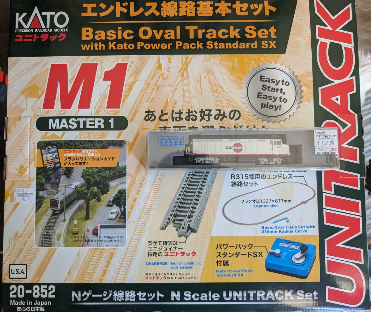
In order to get this up and running, the very first thing I would need is a bit of track and a train to run on that track. I did essentially no research on what I should get beyond knowing that I wanted a DCC enabled n-scale train. I wanted the DCC enable train because designing and installing my own DCC decoder is something that is going to be way down the line, when I start creating my own locomotives, and because I wanted to not have to wonder if it is my controller or the train that doesn’t work. I chose n-scale simply because I don’t have a lot of space to work on this stuff and the more track I can fit onto my dining room table the happier I’ll be. So, I went down to my local train store and got the cheapest starter kit and train that I could find.
In two great strokes of luck, the cheapest DCC locomotive happened to be a Caltrain F40 (i.e., the train I ride to work basically every day) and the cheapest starter kit for track was the Kato Unitrack system. Keeping in theme, I had done zero research on what kind of track I should use and it was only later that I discovered YouTube videos that would generally agree that Kato is the way to go.
Naturally, the first thing I did when I got home was set it up and used the included Kato Power Pack to run it in loops for a few minutes hours. I don’t have a video of this and I’m not planning on recreating the moment, so you’ll have to use your imagination to picture me watching a train go in a circle for a few hours, stupid grin on my face.
With that done, high level plans on how the system would run could be created. To my understanding, there’s two main ways that model trains are controlled today: DC/analog and DCC. Rather than replicating a bunch of information about the differences between those two here, I’ll just link to the DCC Wiki and let them explain. The short version: DC controls trains via the voltage on the track and can only control one at a time whereas DCC sends a signal on the tracks by alternating voltages and can address individual trains. There are some other variants out there but I don’t know much about them and DCC seems to fit all of my needs.
These systems all operate with voltages around 12V, which means that I really don’t want any of this directly connected to my computer, which in turn means we have our two major initial requirements: I need to be able to independently set the rails to both ground and 12V, and I need to be able to control this without a physical connection to my computer. Knowing full well that there are better solutions out there, I grabbed myself an L298 from SparkFun and an HC-05 Bluetooth module at my local electronics shop.
Making the Command Station
The Physical Circuit
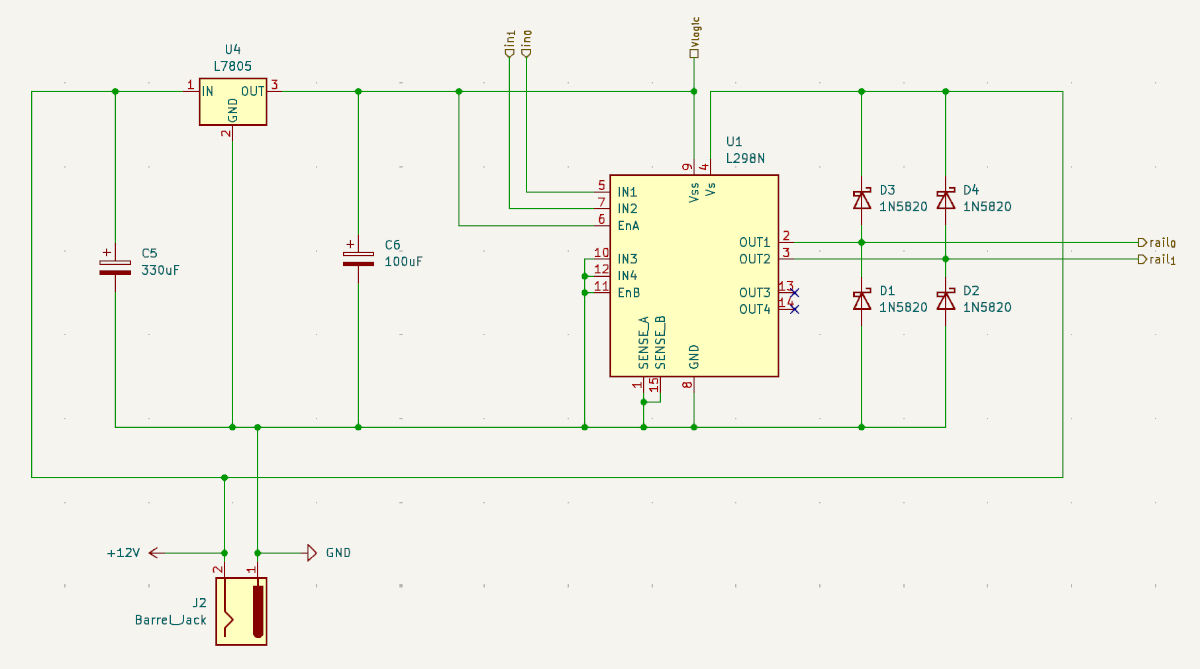
The first step to getting everything running on DCC is to make the Command Station. Or Booster. Or Cab. The terminology starts to fall apart a little bit when you try and apply it to the system that I’m making. So, for this initial portion, I’m going to refer to my laptop as the Cab and the circuit I’m about to describe as the Command Station, with the Booster just not existing. This Command Station is essentially going to be something that can both power an Arduino while modulating the voltages on the track using the L298 h-bridge.
Note | There’s a million tutorials and guides on how h-bridges work, especially the L298, so I’m not going to address that here. The short version is that I can use it to have one of the track’s rails be either 12V or 0V based on whether one of the Arduino’s pins is at 5V or 0V respectively. |
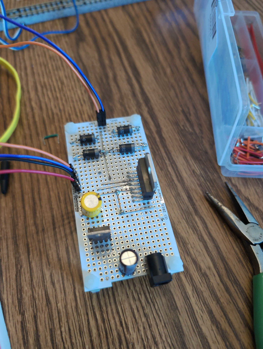
Grabbing a L78M05C because it both matches my needs and was conveniently available at Anchor Electronics, I had everything necessary to make the circuit. If you look at the Design Considerations of the L78M05C datasheet and the Applications section of the L298 datasheet, we’ve pretty much got the whole circuit designed for us. I’m not sure off the top of my head what the values of the capacitors should be if they’re going to be shared between the two chips but we’re not trying to preserve any signals here so we should be able to just slap a larger capacitor in that spot and call it a day. I happen to have several 330μF and 100μF capacitors on hand, so we’ll just use those, and we’re at the stage where pretty much any Schottky diode will work for the flybacks:
Now, to be clear, I technically have a degree in this sort of electronics work but I haven’t touched it in almost ten years. Because of this, I both wildly overestimated my soldering abilities while simultaneously being completely unaware that custom PCBs are now affordable. Last time I looked into custom PCBs, we were talking prices close to $200 just to start production and then $20/board for the first 50 boards, minimum order of 50. I assumed that manually soldering would be the right way to do this and that I would be so much better at it than I am. So, to kick things off right, I attempted to manually figure out the circuit board via pen and paper, assuming I’d be able to fit all of this onto a 1⅞"x1⅞" board. If you can’t tell by the picture below, it didn’t go well.
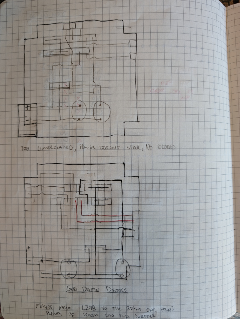
I started to do a hand-drawn circuit board layout for a board that was double the size, but I quickly realized that I would be much better just admitting that it was time to accept that I needed to learn a new technology and learn me a PCB designing program. If you’re wondering how I made the schematic above without knowing one of these programs, then you’ve caught me in a lie - the schematic was also hand-drawn but I lost it, so this blog contains the schematic I used later.
I decided on KiCad because it was both open source and seemed to be relatively highly recommended, so I installed that and started messing around to get a general feel of how things worked. It seemed pretty clear that blue and red lines were the front and back of the board, the vias looked like holes in the perf board, and the components spoke for themselves, so between that I felt like I was in a position to design the layout. I’m not going to show a picture of it here, partially because I don’t think it’s too interesting, partially because the picture to the left would make the layout of this section pretty bad, but mostly because it’s available in the Gitlab Repository. If you’re really curious about the final schematic, you can find it there.
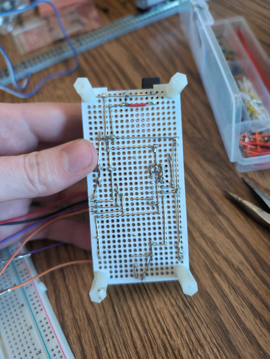
With the design done, it was time for much swearing, burning of fingers, and general terrible soldering. The end result is pretty ugly but everything works and we’re able to generate the DCC signals that we want to be able to generate. I elected to not include a current sensing diode as I don’t have the bits of track that commonly cause short circuits, so the current Command Center is a bit of a risk to use.
Programming the Command Center
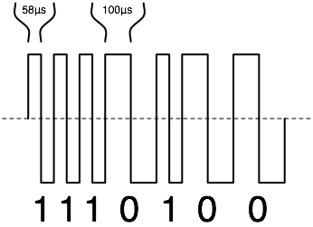
Lets start with the world’s quickest explanation of DCC control. The trains only have two contact points with the rails, the left and right rails, so signals can’t be sent the way most embedded signals happen. I.e., we can’t have a data line that alternates between a high and low value. Instead, we have to alternate which rail is high and which rail is low, generating something that kind of looks like a square wave if you squint a little. The value transmitted by the DCC signal is based on the amount of time between the rising edge of the signal.
The DCC standard states that a 1 nominally has two half periods of 58μs, meaning the time between rising edges for a value of 1 is nominally 116μs.
Seem pretty clear, right?
Well, most other resources say that the nominal time for a 1 is 106μs, which means that either I don’t understand basic math or some conspiracy is happening (or, maybe more realistically, most places are mistakingly referring to the minimum time period as the nominal, which is incorrect).
For a 0, the standard gives a massive range of values in order to enable something called Zero Stretching, but for our purposes we can just use 232μs as the period for 0 in order to make some of the code simpler.
One final thing to mention before we start getting into the Arduino code itself. The DCC specification defines an "idle packet" that can be sent along the rails when there are no other packets to be sent. We’re going to use this packet without talking about what DCC packets look like in general in order to get something up and running quickly - we’ll address the packets themselves later on. If we send the idle packet correctly, the Caltrain’s headlights will turn on and the train won’t move. If we didn’t send the packet correctly, either the train’s lights will stay off or we’ll see the train assume it’s in DC mode and begin to move. Once we have this basic command working, we’ll move on to actually controlling the train and understanding the packets.
We could start by keeping the Arduino code very simple by just writing to the pins and using delayMicroseconds but (1) I don’t think that actually makes the code much cleaner and (2) we’ll very quickly need to move away from that anyway.
We need the output of the packet to happen at very specific time intervals, even if the main logic of the Command Center is doing something else, like communicating with the Cab.
Using PWM is an option but trying to accurately manage the timing of modifying the width seems like an absolute hell, so we’ll just use timer interrupts.
The Arduino runtime doesn’t want us messing with Timer1, which is the only one that can natively represent 58μs intervals, so we will need to modify the prescalar for the timer.
After some quick maths, we write our code:
// The pins to connect to the Command Center
const int IN2 = 2;
const int IN1 = 3;

// The DCC IDLE packet.
const byte IDLE[] = {
  0b11111111,
  0b11110111,
  0b11111000,
  0b00000001,
  0b11111111,
};

void setup()
{
  pinMode(IN1, OUTPUT);
  pinMode(IN2, OUTPUT);

  // Disable interrupts
  cli();

  // Clear the timer settings
  TIMSK2 = 0;
  TCCR2A = 0;
  TCCR2B = 0;
  OCR2A = 0;

  // Turn on CTC mode
  TCCR2A = (1 << WGM21);

  // Set the prescaler to be 8 so that 58us fits within 256
  TCCR2B |= (1 << CS21);

  // Trigger every 58us
  OCR2A = 115;

  // Enable timer compare interrupt
  TIMSK2 = (1 << OCIE2A);

  // Enable interrupts
  sei();
}

// The timer interrupt.
//
// This will trigger every 58us, which is half the time of a `1` and a quarter
// of a `0`, so it internally contains a small state machine to track the
// appropriate rail levels.
ISR(TIMER2_COMPA_vect)
{
  // The current position.
  static unsigned int IDX = 0;

  // The number of interrupts that have happened on this bit.
  static unsigned int COUNT = 0;

  // Calculate the active bit.
  unsigned int bit_idx = IDX & 0b111;
  unsigned int byte_idx = (IDX >> 3) & 0b111;
  byte bit = (IDLE[byte_idx] >> (7 - bit_idx)) & 0b1;

  // Set the pins based on the bit.
  if(bit) {
    if(COUNT == 0) {
      digitalWrite(IN1, HIGH);
      digitalWrite(IN2, LOW);
      COUNT += 1;
    } else {
      digitalWrite(IN1, LOW);
      digitalWrite(IN2, HIGH);
      COUNT = 0;

      IDX += 1;
    }
  } else {
    if(COUNT == 0) {
      digitalWrite(IN1, HIGH);
      digitalWrite(IN2, LOW);
      COUNT += 1;
    } else if(COUNT == 1) {
      COUNT += 1;
    } else if(COUNT == 2) {
      digitalWrite(IN1, LOW);
      digitalWrite(IN2, HIGH);
      COUNT += 1;
    } else {
      COUNT = 0;
      IDX += 1;
    }
  }

  // Make sure the address is valid.
  if(IDX >= 0b101000) {
    IDX = 0;
  }
}

void loop() {}
Hooking up the Arduino to the board and the board to the tracks, we do in fact see the train turn on its headlights without moving anywhere. Success! I’d take a picture of it and add it here, except for the fact that this section is already pretty crowded with non-prose content. Instead, we’re going to move on to adding the Bluetooth connection so we can control the train remotely. That section also happens to be the experience that really motivated me to actually write this blog.
Connecting via Bluetooth
I don’t want to have my computer physically connected when this thing runs, since there’s just too much of a chance that I will accidentally send 12V straight into my laptop’s USB port. So, we’re going to follow every HC-05 guide on the internet (like this one) and get things up and running. Simple, right? Everything is built into the module, shouldn’t have any issues, right?
Wrong.
Sometime between when the HC-05 was first created and early-to-mid 2024, something about the Bluetooth stack on macOS changed.
I have in my possession two MacBooks, one circa 2015 running macOS Monterey 12.7.4 and another circa 2019 running macOS Sonoma 14.4.1, and both experience this issue.
What is the issue?
The HC-05 connects but never transmits or receives data.
I was able to rule out issues with the Arduino by directly connecting the tx and rx pins on the HC-05.
I was able to rule out the HC-05 itself by using the "Serial Bluetooth Terminal" Android application like all of the tutorials said.
I even know it wasn’t something with the specific HC-05 module because I tried multiple of them.
The problem is with the laptops.
Of course, if you do some Google searching, you’ll find people saying MacBooks don’t support SPP anymore. This, of course, is wrong. How do I know? Because I can almost always get the HC-05 to connect to the MacBook but very rarely can I get it to actually transfer any information, but it does happen.
Do I have a solution to this? Not really. But I have noticed two things:
Sending data seems to be most successful when pairing with the HC-05 the first time.
Writing to the
/dev/tty.HC-05(or whatever you named the module) only works if something has it open for reading as well.
So, every time I want to connect to the HC-05 via the laptop, I completely forget the device and repair the two.
When I want to transmit data over the connection, I make sure I either have my program open the TTY in read/write mode or I have screen open it.
I know this isn’t really a good explanation or resource for resolving the problem, but I was having so much trouble finding anything that even acknowledged that this problem exists that I wanted to put out a blog just so that people can be assured that someone else had this same problem.
If you don’t have this issue then please let me know what might be different about your setup that might help me debug this issue.
Because of all this, I am going to skip the section about the TUI app I created in order to control the train. If you want to see it now, then the code for it is available on Gitlab and it doesn’t actually require the Bluetooth to be connected to run (at least, not on my machine). So, hopefully someone finds this section reassuring, if not helpful, and we’ll move on. From this point forward, just know that I am using the "Serial Bluetooth Terminal" application on my phone to control the train.
Melting the Bluetooth (and an Arduino, and a Raspberry Pi Pico)
This is less about the steps in making a DCC controller and more just a story that I want to tell people. When I was trying to debug the above Bluetooth issues, I noticed that my Bluetooth module wasn’t flashing its LEDs anymore. "Curious," I thought to myself, "I wonder why that could be." I spent some time trying to figure out what was going on but wasn’t able to determine the issue.
Thinking that I must have ruined my HC-05 somehow, I rushed to Anchor Electronics mere moments before they closed for the weekend and bought myself a new HC-05. I came home, hooked it up, and then immediately saw the magic smoke leave my Arduino. Being the brilliant man I am, I immediately assumed that the previous HC-05 must have ruined my Arduino, so I plugged in a Raspberry Pi Pico that I happened to have on hand. This also somehow released the magic smoke.
Ooh.
Cool.
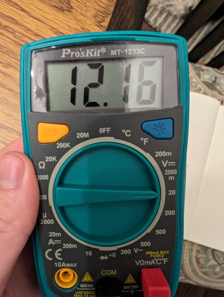
My breadboard power supply’s 5V output sent 12V straight into the 5V pin of my Arduino, the VBUS pin on the Pico, and the VCC pin of the HC-05.
Lovely.
Transitioning to a Pico
This is the final section of the blog post - it’s gotten a little long, hasn’t it? It feels that way to me but, again, I don’t like writing. At this point, I had no Arduino and I’m struggling with the HC-05, so it seemed time to move on to a different microcontroller. I happened to have two on hand: an ESP32 and a Raspberry Pi Pico (a different one, not the one I fried).
On the surface level, the two seemed pretty close to identical. Both have Wi-Fi and Bluetooth Low Energy to replace the HC-05 struggles I’ve been having. Both are dual core, relatively low power consumption (remember: I have several amps of 12V power available) and the Rust support is approximately equal between the two. So, it really boiled down to which one I thought I could get up and running quicker because, up until I melted the Arduino, I had a train responding to DCC commands and I wanted to keep playing.
So, getting this up and going required learning a little more about DCC command packets. The DCC standard for basic locomotive control is actually fairly straightforward. The previous Arduino code allowed us to send generic bytes as a DCC packet, so we just need to make sure that the bytes have the right bits. For basic speed and direction, we care about this packet:
111111111111 0 0AAAAAAA 0 01DCSSSS 0 EEEEEEEE 1
    Preamble   Byte One   Byte Two      Error

A: Train Address
D: Direction
C: Speed*
S: Speed
Reading from left to right, that is the order the bytes need to be transfered or, in other words, bytes are sent in big-Endian order.
The address is the address that the train is programmed to respond to and, in most cases, that is a default value of 3.
The speed portion is a little bit weird in that the C bit is sometimes the least-significant bit of the speed value and sometimes it’s headlight control.
The error portion is just an XOR of the first two bytes.
This doesn’t quite fit into 32 bits, but five bytes isn’t too bad of a deal.
At this point, I’m going to continue using the HC-05 module because, something that was news to me, BLE isn’t nearly as straightforward as the Bluetooth SPP. The "protocol" that we’ll be using for sending command on the serial port is just a positive or negative integer character representing the "notch" we want to put the engine’s pretend throttle in, keeping it simple to interface with using the "Serial Bluetooth Terminal" mentioned previously.
We’re also going to take advantage of the message queues that the Pico’s utility library provides in order to communicate information to the timer interrupt. All that being said, here’s the code:
/// A basic DCC controller
///
/// Speed and Direction Packet for Locomotive Decoders:
/// 11111111|1111 0 0AA|AAAAA 0 01|DCSSSS 0 E|EEEEEEE 1
#include <string.h>
#include <stdio.h>
#include "pico/stdlib.h"
#include "pico/util/queue.h"
#include "hardware/gpio.h"
#include "hardware/uart.h"

#define IN0 27
#define IN1 26

#define TX 0
#define RX 1
#define UART_ID uart0
#define BAUD_RATE 9600

#define FIFO_LEN 32

/// The DCC IDLE packet sent when no other commands are required.
const uint8_t DCC_IDLE_PACKET[] = {
	0b11111111,
	0b11110111,
	0b11111000,
	0b00000001,
	0b11111111,
};

/// A debugging packet that drive Engine #3 at 50%.
const uint8_t FORWARD_3_50_PACKET[] = {
	0b11111111,
	0b11110000,
	0b00011001,
	0b10010000,
	0b11001111,
};

/// The state of a DCC "booster".
struct booster
{
	/// The queue used to receive new packets.
	queue_t queue;

	/// The current DCC command.
	uint8_t packet[5];

	/// The current bit index.
	unsigned int idx;

	/// The number of DCC cycles we've been on this bit.
	unsigned int cycles;
};

/// Initializes a `booster`.
struct booster create_booster()
{
	struct booster state = {0};
	queue_init(&state.queue, sizeof(uint8_t) * 5, FIFO_LEN);
	memcpy(state.packet, DCC_IDLE_PACKET, 5);

	return state;
}

void init_bluetooth();
void init_rails();
void swap_rails();
void init_dcc(struct booster*);
bool boost_dcc(struct repeating_timer*);

int main()
{
	stdio_init_all();

	init_bluetooth();

	struct booster state = create_booster();
	init_rails();
	init_dcc(&state);

	for(;;) {
		// I'm pretty sure that `uart_getc` will see '\r', '\n', and any other control character. We
		// want to ignore those, so we'll silently discard anything that isn't `[-7, 8]`.
		uint8_t speed_or_negative = uart_getc(UART_ID);
		uint8_t forward = 0;
		uint8_t speed = 0;

		if(speed_or_negative == '-') {
			forward = 0;
			speed = uart_getc(UART_ID);
		} else if(speed_or_negative == '+') {
			forward = 1;
			speed = uart_getc(UART_ID);
		} else if(speed_or_negative >= '0' && speed_or_negative <= '7') {
			forward = 1;
			speed = speed_or_negative;
		} else {
			if(speed_or_negative == '8') {
				// TODO: This is kludge because I want to see what it does. Do something smarter.
				uint8_t byte = 1;
				queue_add_blocking(&state.queue, &byte);
				uart_puts(UART_ID, "OK\n");
			}
			continue;
		}

		uint8_t byte = 0b10001 | (forward << 5) | ((speed - '0') << 1);
		queue_add_blocking(&state.queue, &byte);
		uart_puts(UART_ID, "OK\n");
	}
}

/// Initializes the Bluetooth UART.
void init_bluetooth()
{
	uart_init(UART_ID, BAUD_RATE);
	gpio_set_function(TX, GPIO_FUNC_UART);
	gpio_set_function(RX, GPIO_FUNC_UART);
}

/// Initializes the rail GPIOs
void init_rails()
{
	gpio_init(IN0);
	gpio_set_dir(IN0, GPIO_OUT);
	gpio_init(IN1);
	gpio_set_dir(IN1, GPIO_OUT);

	gpio_put(IN0, 1);
	gpio_put(IN1, 0);
}

/// Swaps the polarity of the rails.
void swap_rails()
{
	gpio_xor_mask((1 << IN0) | (1 << IN1));
}

/// Initializes the DCC timer.
void init_dcc(struct booster* state)
{
	static struct repeating_timer TIMER;
	add_repeating_timer_us(-58, boost_dcc, state, &TIMER);
}

/// The callback for managing DCC transmission.
bool boost_dcc(struct repeating_timer* t)
{
	struct booster* booster = t->user_data;

	unsigned int bit_idx = booster->idx & 0b111;
	unsigned int byte_idx = (booster->idx >> 3) & 0b111;
	uint8_t bit = (booster->packet[byte_idx] >> (7 - bit_idx)) & 0b1;

	// TODO: This state machine could probably be done in a smarter way.
	unsigned int idx = booster->idx;
	unsigned int cycles = booster->cycles;
	if(bit) {
		swap_rails();
		if(cycles == 0) {
			cycles += 1;
		} else {
			cycles = 0;
			idx += 1;
		}
	} else {
		if(cycles == 0 || cycles == 2) {
			swap_rails();
			cycles += 1;
		} else if(cycles == 1) {
			cycles += 1;
		} else {
			cycles = 0;
			idx += 1;
		}
	}

	if(idx >= 0b101000) {
		idx = 0;

		uint8_t speed;
		if(queue_try_remove(&booster->queue, &speed)) {
			// The main loop manages converting from the UART to the bytes that we want to assign,
			// so we can just bit fiddle here.
			uint8_t b1 = 0b00000011;
			uint8_t b2 = 0b01000000 | speed;
			uint8_t e = b1 ^ b2;

			booster->packet[0] = 0b11111111;
			booster->packet[1] = 0b11110000;
			booster->packet[2] = 0b00011001;
			booster->packet[3] = (speed << 2) | (e >> 7);
			booster->packet[4] = (e << 1) | 0b1;
		} else {
			memcpy(booster->packet, DCC_IDLE_PACKET, 5);
		}
	}

	booster->idx = idx;
	booster->cycles = cycles;

	return true;
}
In the future, this code is probably either going to transition to assembly or to Rust, depending on which I think will be more fun, but this was quick to get going and I officially have a train that I can control remotely.
What Next?
The plan is to continue writing posts like this as I make more progress on the system. I’d like to imagine I’ll get better at writing them as time goes on but we’ll see what happens.
At this point, the next thing I’m working on is automating a turnout so that it can be controlled over DCC and I would say I’m about half way done with physically completing that - I just need to start writing about it. I definitely want to be able to play with the turnout soon, so I expect that one won’t be weeks delayed like this one was. After that, it’s on to actually connecting via the Pico’s BLE, then making actual PCBs for the DCC encoder/decoder, and then probably onto some form of block detection.
As a reminder, I have posted this on Reddit for comments.