Automated Switching
This is coming in hot off the tail of my first blog post. So hot, in fact, that I basically only got up to get myself something to drink and then sat back down to keep writing. Why? Because I’ve already done half the things I want to talk about in this blog and I’m very excited to finish them up.
I want DCC controlled turnouts.
If I was doing model railroading the "normal" way, I’d grab myself Digitrax DS51K1 and call it a day. They’re designed to work with Kato turnouts, are small enough to fit inside of the Unitrack, and not particularly expensive. But that’s not why we’re here - we’re here to make our own.
Anatomy of a Turnout
Because I’m using Unitrack, I scoured the internet for any information about how they work. From the back of my starter kit, I knew that they were powered somehow but all I was able to find online is that they used a "two wire solenoid," which is a good thing to know but it wasn’t enough that I really felt I could start designing the system. There were a few other resources that were slightly more helpful (like this T-Trak guide) which gave me a little bit more information but, for the most part, I couldn’t find anything telling me anything about the solenoid inside of the turnouts. Naturally, this meant another visit to The Train Shop to pick up the track.
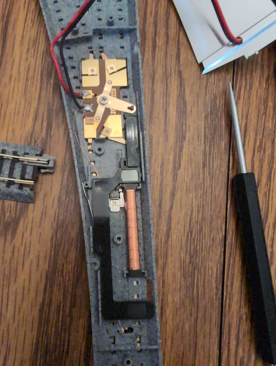
Kato Unitrack #6 Electric Turnout purchased, I headed home to open the thing up and see what we were working with. Looking at it, it seem pretty clear that why I wasn’t able to find any information about what kind of solenoid was inside the turnout - it’s literally just copper wire wrapped around a metal core. I am aware that that’s exactly what a solenoid is but for some reason I was expecting a fully packaged unit like I had seen in the "Solenoid" section of various electronics stores.
Poking around a bit, it’s pretty obvious that the top portion is the section that physically controls what rail connects to the frog. The bottom portion is just the solenoid that twists a small pin to move the points from side to side. Thinking forward to when I have some PCBs to fit in here, it seems like the best plan of attack would be to cut the feeder wires short and stick the circuit where they used to be, leaving everything else completely untouched. But that’s for a future update. For now, I just need to get this moving via some breadboard circuit.
There are a few important things I did learn that you’re probably not going to find online anywhere else:
The back plate is crucial to the operation of the switch, to the point where just opening the back is probably going to cause the pin to unhook and break your switch.
The pin controlling the switch is exactly the required length to operate, so fixing an unhooked pin is an absolute pain.
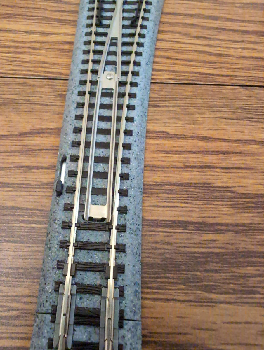
You can get the pin in there and think you’ve fixed your switch, but when you turn it over and try to hook it up, you’ll find that the points don’t fully connect (see picture).
The turnout is rated for "Maximum DC36VA", the Kato switch machine is rated for "Maximum DC15VA", and the maximum contact time when using the switch machine is one second. It says this on the back of the box.
I honestly am not entirely sure what to do with that last bit of information. I suppose that I could measure the resistance of the solenoid and calculate how much time it will take to deliver that amount of power but I don’t think I’ll be able to get any useful number using the multimeter that I own. What I’ll do instead is realize that I’m providing the same voltage as the switch machine (I am actually using the wall adapter from the starter set) and that is allowed to make contact for a full second, so I’ll just turn on the solenoid for less time than that and call it a day. Let’s say 50ms and see how that works out.
Of course, after I fix the switch so it actually works.
Given that I had a number, it was time to hook up a new Arduino to try and throw the switch electronically. I wish I had taken a picture of the circuit I made so that I could include it here but, alas, this is one of the reasons why I want to catch the blog up to reality. The circuit is destroyed and I’m not going to recreate it for the photoshoot. What I will do is link to the solenoid tutorial that I used to help me construct my circuit (mostly helping me pick what transistors to pick up from my local electronics shop).
The code for throwing the switch is incredibly simple, in that we just set a pin HIGH, wait 50ms, and then set it LOW.
The one catch that I found was that I did need to delay before setting the pin high otherwise the switch wouldn’t throw, which I assume to be a product of me futzing around with the physical connection.
For the sake of completeness, here’s the Arduino sketch:
const uint8_t solenoidPin = 8;

void setup() {
  pinMode(solenoidPin, OUTPUT);
  delay(5000);
  digitalWrite(solenoidPin, HIGH);
  delay(50);
  digitalWrite(solenoidPin, LOW);
}

void loop() { }
With that done, we know we can throw the turnout, we just need to connect the Arduino to the rails in a way that can receive signals from the Command Center. I don’t see any reason to try and include additional wires or another wireless chip, so this is where a homebrew, DIY DCC decoder comes in.
Decoding DCC
The first step in getting a decoder up and running is figuring out how to power the decoder from the rails.
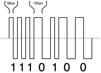
If you remember from the last blog post, the DCC signal is actually a square-ish wave where the rails alternate between being the full 12V and being ground.
The amount of time between this alternating determines whether or not the incoming value is a 0 or 1.
In respect to how we’re going to power our decoder, this means that there isn’t any wire for us to hook up to that represents a constant +12V or even a constant ground.
For those of you familiar with electronics, you probably already know where this is headed: a bridge rectifier.
I think the usage of the rectifier is the uncontroversially correct choice here, so I’m going to skip past the explanation, justification, and little breadboard test I did to make sure that everything worked. The same goes with how I’m going to convert from 12V (minus some voltage drop across the diode) to a 5V line that the microcontroller can use: one of the L78M05Cs that I happen to have on hand. Yes, I know that the Arduino can take 12V as input, but this felt a little closer to the circuit I will eventually have to make and it really isn’t much overhead. The more interesting part is how I’m going to convert the DCC signal into something that can be handled on an input pin.
Logic Level Shifting
My first thought was to grab a Logic Level Shifter, hook it up to one of the DCC lines, and call it a day.
This almost works.
Painfully almost works.
The problem with those logic level shifters is that they use pull-up resistors to default the pins to HIGH and then when one of the pins is pulled down, it pulls the other down as well (more or less).
In most cases, I imagine that would work very well and, honestly, I think it’s quite elegant.
Except here we’re dealing with negative voltage.
Tip | While you’re at Pololu for the logic level shifter, you might as well grab several Mini Tamiya Male Plugs since Kato uses female Mini Tamiya plugs for all of the Unitrack plugs. They don’t quite fit correctly because the hook on the Kato is larger than the receiver on the Pololu but it’s so much better than stuffing wires into crimps. |
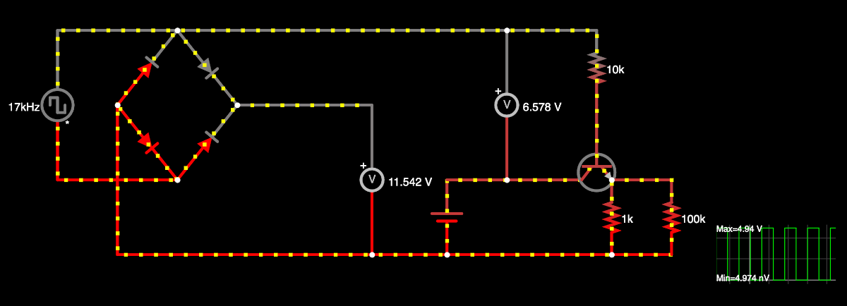
If we simulate this situation on Falstad, the negative voltage is pretty clear. The problem is that the rectifier causes our DC ground to be at a slightly higher voltage than the rail that is acting as ground, giving us the negative voltage. When I recreated this circuit using the 1N5817 diodes I had on hand, the results were almost exactly the same as what Falstad gave. This is juuuust outside the range of what an Arduino can handle but, as a rule, it seems better to keep negative voltages away from DC circuits as much as possible.
There might be a way to fix this using passive components but I wasn’t able to find it while playing around. I did have moderate success using a half-wave rectifier and a sufficiently large capacitor instead of a full-wave rectifier but nothing was satisfactory. In the end, I decided to admit that if I was fine with an active component in the logic level shifter, I should be fine with an active component that eliminates the logic level shifter. Fortunately, we don’t need the signal to be bidirectional and we don’t really care if the signal is inverted, so we can use basically whatever transistor we want.
The transistor I want to use is a MOSFET but I don’t have any of those on hand. What I do have on hand are a few TIP120 NPN transistors so I’ll throw one of those on the breadboard. Hooking that together in simulation, I get this.
If you look at that and think something is funky with it, then we’re on the same boat.
I don’t recall much about my never-used-it-professionally-or-even-at-all-really electrical engineering courses, but I do remember that NPN transistors should go between the load and ground, not between the source and the load.
But, fiddle as I might, I couldn’t get a "correctly placed" NPN transistor working in a way that put the LOW values in an Arduino’s LOW range and the HIGH values in the Arduino’s HIGH range.
The PNP transistors were another story - I never got them in the correct ranges at all.
Using MOSFETs in simulation, I can get things were it looks right and it works right, but I don’t have any of those on hand.
So, the plan is to continue with my funky circuit and hope someone corrects me ask someone to check it out before I commit this all to a PCB.
Worst case, I fry a few electronic components and I have to get some more.
Note | At this point, the blog is caught up to reality. Instead of describing things I did over the weekend and trying my best to make it sound like I’m live reporting, we’re actually live reporting now. No more staged photos, no more dancing around with tenses, this is the real deal. |
Packet Detection
So we have a way to power the Arduino and we have an input that is the top half of the DCC signal, so all we need to do is detect the rising edges and determine the period. If we ignore the fact that I eventually want this to be run on an ATtiny4, then we’re actually looking at a pretty simple task since the ATmega328P has two timers that we can use — one for counting the microseconds between rising edges and one for timing how long to turn on the solenoid. To start off with, lets generate a very slow square wave on the tracks and see if we can simply get rising edge detection working (code for the square wave generation is left as an exercise for the reader).
The Arduino documentation says that only pins 2 and 3 are interrupt pins.
Looking at the ATmega documentation, basically all of the pins can be use for interrupts.
The difference here is the difference between INT and PCINT and might matter down the road, but for now the Arduino has more than enough pins for the task so we’ll just ignore the issue and do the easiest thing.
const int DCC = 3;
const int LED = LED_BUILTIN;

volatile uint8_t BLINKS = 0;

void set_blinks()
{
  BLINKS = 3;
}

void setup()
{
  pinMode(LED, OUTPUT);
  pinMode(DCC, INPUT);

  attachInterrupt(digitalPinToInterrupt(DCC), set_blinks, RISING);
}

void loop()
{
  if(BLINKS > 0) {
    digitalWrite(LED, HIGH);
    delay(250);
    digitalWrite(LED, LOW);
    delay(250);
    BLINKS -= 1;
  }
}
If this is hooked up to a square wave generator with a 5s period, I expect to see the built-in LED on the Arduino blink three times every ten second. When I first went to test the program, I was actually only seeing the LED blink once every ten seconds and I couldn’t figure out why. Turns out, I had the 5V source plugged into a disconnected pin and so the only power for the Arduino was coming in through the interrupt pin. Luckily, nothing seems to be fried and correcting my jumper wires shows me the three blinks I am expecting to see.
This is nice and all, but can it react fast enough to actually decode DCC? There are a few ways that I might want to go about testing this. One is to focus on the DCC idle packet and respond to that. The problem with this plan is that the DCC idle packet is going to be transmitted about 1,000 times a second and a human observer would never be able to notice any kind of LED change at that rate, so I’d have to have it trigger just once. But, honestly, with something happening that often I wouldn’t be wildly surprised if bad code lead to the condition being satisfied erroneously at some point and giving me a false positive. Instead, we’ll lean on the code that already exists and have it toggle the LED for any signal addressed to Train #3. That way, I can use the same interface that I’ve been using to play with the train for testing the DCC decoding. Once that’s done, it should be a fairly small change to adjust the address its listening to and decoding the direction bit (or however accessory decoders generally interpret packets — we’ll get there later) in order to throw the turnout.
So, to get this working we need to modify the edge detection code. For the moment, we’re not going to worry about power consumption, so we just need an algorithm for detecting the correct packet based on interrupts and timing. We’ll start off just blinking the built-in LED to indicate that we received a packet and what direction it was.
const int DCC = 3;
const int LED = LED_BUILTIN;

// The DCC address for this decoder
const uint8_t SWITCH_ADDRESS = 3;

// The flag used to indicate the switch should be thrown. The sign of the
// byte is used to indicate the direction.
volatile int8_t DIRECTION = 0;

void dcc_decode()
{
  static uint8_t SIGNAL[] = { 0, 0, 0, 0, 0};
  static unsigned long LAST_EDGE_TIME = 0;
  unsigned int time = micros();

  // This has the potential to fail every ~70 minutes due to overflow.
  // This really only means we may miss a single packet in that time
  // so it shouldn't be an issue.
  unsigned int period = time - LAST_EDGE_TIME;
  LAST_EDGE_TIME = time;

  // If `period < 104` or `128 < period < 190`, then this isn't a valid
  // DCC bit. Lots of things could be going on to cause this to happen
  // and many of them are valid, but we don't expect to see those right
  // at this point in development. We'll just ignore that case.
  uint8_t bit = period < 128;
  SIGNAL[0] = (SIGNAL[0] << 1) | SIGNAL[1] >> 7;
  SIGNAL[1] = (SIGNAL[1] << 1) | SIGNAL[2] >> 7;
  SIGNAL[2] = (SIGNAL[2] << 1) | SIGNAL[3] >> 7;
  SIGNAL[3] = (SIGNAL[3] << 1) | SIGNAL[4] >> 7;
  SIGNAL[4] = (SIGNAL[4] << 1) | bit;

  // Extract the bytes from the packet when a valid packet is found
  bool valid_preamble = SIGNAL[0] == 0xFF && (SIGNAL[1] & 0xC0) == 0xC0;
  if(!valid_preamble) { return; }

  uint8_t byte_start_bits = (SIGNAL[1] & 0x8) | (SIGNAL[2] & 0x4) | (SIGNAL[3] & 0x2);
  if(byte_start_bits != 0) { return; }

  uint8_t address = (SIGNAL[1] << 5) | (SIGNAL[2] >> 3);
  if(address != SWITCH_ADDRESS) { return; }

  uint8_t data = (SIGNAL[2] << 6) | (SIGNAL[3] >> 2);
  uint8_t error = (SIGNAL[3] << 7) | (SIGNAL[4] >> 1);
  if(error != (address ^ data)) { return; }

  // Valid packet addressed to us.
  DIRECTION = (data & 0b00100000) ? 1 : -1;
}

void setup()
{
  pinMode(LED, OUTPUT);
  pinMode(DCC, INPUT);

  attachInterrupt(digitalPinToInterrupt(DCC), dcc_decode, RISING);
}

void loop()
{
  if(DIRECTION < 0) {
    // Long
    digitalWrite(LED, HIGH);
    delay(1000);
    digitalWrite(LED, LOW);
    delay(250);

    // Short
    digitalWrite(LED, HIGH);
    delay(250);
    digitalWrite(LED, LOW);
    delay(250);

    // Short
    digitalWrite(LED, HIGH);
    delay(250);
    digitalWrite(LED, LOW);
    delay(2000);

    DIRECTION = 0;
  } else if(DIRECTION > 0) {
    // Short
    digitalWrite(LED, HIGH);
    delay(250);
    digitalWrite(LED, LOW);
    delay(250);

    // Long
    digitalWrite(LED, HIGH);
    delay(1000);
    digitalWrite(LED, LOW);
    delay(250);

    // Short
    digitalWrite(LED, HIGH);
    delay(250);
    digitalWrite(LED, LOW);
    delay(2000);

    DIRECTION = 0;
  }
}
The code works as expected but I am starting to have issues with the train losing power intermittently. I’m pretty sure it’s not the new circuit that I’ve connected to the track because the issue exists even when it’s disconnected, so I wonder if my terrible soldering job on the Command Center is coming into play. Regardless, the whole thing works well enough that it’s time to hook up an h-bridge to the decoder to throw the turnout.
Throwing the Switch
I have a bunch of spare TIP120s and TIP125s so I could create an h-bridge out of those. I also have a few spare L298Ns that would work. But I’m feeling particularly lazy - I don’t want to deal with adding that many new parts to the breadboard. When I bought the logic level shifter, I also purchased an MP6550 motor driver carrier from Pololu to replace the L298 later down the road. The L298 is an ancient chip that is large, inefficient, and requires external components to be hooked up correctly. The MP6550, on the other hand, is smaller, more efficient, more powerful, and has built-in flyback diodes for slightly less money. I’ll need to evaluate it for sending DCC commands soon but right now I may as well use to to drive the solenoids.
The changes to the Arduino code are relatively minor. Instead of blinking the LED, we just raise a PIN for a few milliseconds and change what address the decoder responds to:
const int IN2 = 8;
const int IN1 = 9;
const uint8_t SWITCH_ADDRESS = 128;

void loop()
{
  if(DIRECTION < 0) {
    digitalWrite(IN2, HIGH);
    delay(50);
    digitalWrite(IN2, LOW);
    delay(1000);

    DIRECTION = 0;
  } else if(DIRECTION > 0) {
    digitalWrite(IN1, HIGH);
    delay(50);
    digitalWrite(IN1, LOW);
    delay(1000);

    DIRECTION = 0;
  }
}
Things are slightly more complicated on the Pico’s end of things. We can’t hard-code the address anymore and we have to accept an input that isn’t a number. Because I haven’t fixed the Bluetooth situation on my MacBooks yet, I’ll still be using the Bluetooth Serial Terminal app and I don’t want to have to have different inputs to throw the switch each direction, so there will be the tiniest bit of logic to keep track of that state as well. Below are some of the changes. As always, all of the source code will be available in full in the Gitlab repository.
struct booster create_booster()
{
	struct booster state = {0};
	queue_init(&state.queue, sizeof(uint16_t), FIFO_LEN);
	memcpy(state.packet, DCC_IDLE_PACKET, 5);

	return state;
}

int main()
{
	// ...

	bool turnout = false;
	uint8_t message[255] = { 0 };

	for(;;) {
		uart_puts(UART_ID, "Waiting for input...\n");

		uint8_t first = uart_getc(UART_ID);
		uint8_t address = 0;
		uint8_t data = 0;

		if(first == '-' || first == '+' || (first >= '0' && first <= '7')) {
			uint8_t direction = (first != '-');
			uint8_t speed = first;
			if(first == '-' || first == '+') {
				speed = uart_getc(UART_ID);
			}

			if(speed < '0' || speed > '7') {
				sprintf(message, "invalid speed: %c\n", speed);
				uart_puts(UART_ID, message);
				continue;
			}
			speed = (speed - '0') << 1;

			sprintf(message, "address=3 direction=%u speed=%u\n", direction, speed);
			uart_puts(UART_ID, message);

			address = 3;
			data = 0b01010000 | (direction << 5) | speed;
		} else if(first == 's') {
			turnout = !turnout;
			address = 128;

			sprintf(message, "address=128 direction=%u\n", turnout);
			uart_puts(UART_ID, message);

			data = ((uint8_t) turnout) << 5;
		} else {
			sprintf(message, "unknown command: %c\n", first);
			uart_puts(UART_ID, message);
			continue;
		}

		uart_puts(UART_ID, "adding to queue\n");
		uint16_t address_and_data = (((uint16_t) address) << 8) | data;
		queue_add_blocking(&state.queue, &address_and_data);

		sprintf(message, "address_and_data=0x%x\n", address_and_data);
		uart_puts(UART_ID, message);
	}
}

/// The callback for managing DCC transmission.
bool boost_dcc(struct repeating_timer* t)
{
	// ...

	if(idx >= 0b101000) {
		idx = 0;

		uint16_t address_and_data;
		if(queue_try_remove(&booster->queue, &address_and_data)) {
			uint8_t address = address_and_data >> 8;
			uint8_t data = address_and_data & 0xFF;
			uint8_t error = address ^ data;

			booster->packet[0] = 0b11111111;
			booster->packet[1] = 0b11110000 | (address >> 5);
			booster->packet[2] = (address << 3) | (data >> 6);
			booster->packet[3] = (data << 2) | (error >> 7);
			booster->packet[4] = 0b1 | (error << 1);
		} else {
			memcpy(booster->packet, DCC_IDLE_PACKET, 5);
		}
	}

	// ...
}
If you couldn’t tell from the new sprintf statements, I had a little bit of work debugging this.
Turns out, I was making the queue_t items about four times their actual size which lead to a deadlock.
It wasn’t fun to debug but that’s what you sign up for when you use C, I guess.
But, with that out of the way, it’s time to show the video.
What’s Next?
I’ve noticed that the train occasionally acts like it isn’t receiving power and then switches into (what I assume) is analogue mode. I’m not sure why this is happening but I can think of a few possibilities. The tracks haven’t been out of the box for very long but I haven’t cleaned them or the train a single time, so maybe I should pull out the track cleaning tool that came with the Kato starter set. It could also be that the Command Center plugs into the track at a point that is almost as far as it possibly could be from the buffer at the end of the spur when the switch is thrown. I’ll try a few things along these lines and, if nothing works, I’ll take the train to my local model railroad club and see if someone there can test the train or give me suggestions.
Beyond that, I won’t be able to work on anything physical until the start of July, so I guess I’ll be designing some PCBs to order in a month or two and figuring out how to connect to the Pico W’s BLE. I might also spend a little bit of time figuring out how to put the decoder Arduino into sleep mode in order to conserve power but that doesn’t seem terribly important at this point. Unless, of course, the extra power consumption is the source of my train problem.
As always, this is posted to Reddit for comments.